Table of Contents
|
1: Lab Safety Unit
2: Basics of Energy/Electricity 3: Maglev Vehicle Project 4: Current Indicator 5: LED Brightness Control 6: Light Activated LED 7: Storage of Electrons 8: Speaker Action 9: Diode Tester 10: SCR Checker 11: NPN Transistor 12: PNP Transistor Checker 13: Transistor Oscillator 14: Blinking Light 15: Student Free Choice Lab 16: Safety, Use of Power Sources and Meters 17: Sources of Electricity 18: Switches and Switching Circuits 19: Ohms Law 20: Power, Heat, Light 21: Robotics 22: Conclusion |
|
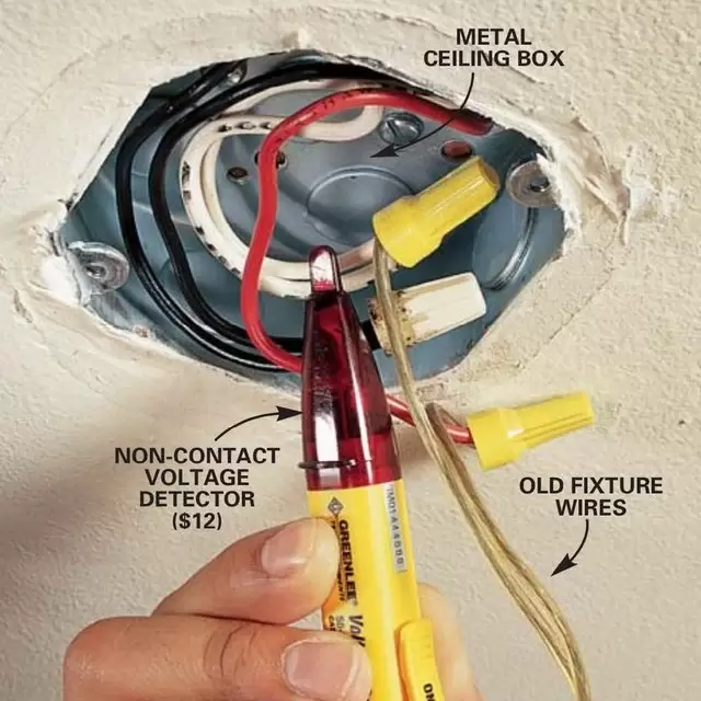
LAB Safety unit
|
The safety unit note sheet was very simple to do. I've already done these notes before once, and the machines showcased in the notes I've done several times before.
|

|
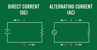
Basics of electricity
|
One of the first things we learned over the course of the class was the basics of electricity. We learned the concepts of magnetism, polarization, voltage, current, resistance, AC, DC, conductors, and insulators.
|
|
MAGLEV Vehicle design challenge project
MAGLEV Vehicle Design Process
What:
The goal of the MAGLEV Project, was to make a vehicle that floats using magnets, and go all the way down the track three times, without any human interference. The biggest challenge of the project for me at least, was making a car that would fit perfectly into the track.
How:
The first two models I made were both 3D printed, but both fell short, one was too wide, and one wasn't wide enough. I decided to take the tower from the first 3D print, and transfer it onto the actual car.
It took me a little while to get the wiring right, at first I had it moving backwards and barely moved, the second time, it was on right and moving forwards... and then it rammed straight into a wall and was destroyed.
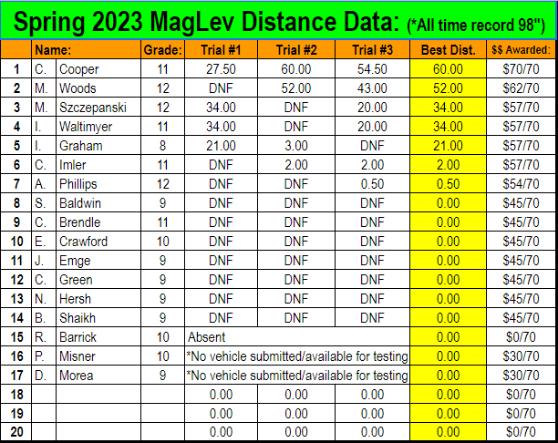
Soon enough I got it back together and the car was going 120-150 inches on the test runs!
Race Day:
On race day, tragedy struck, the car, had stopped going 120 inches, and only went 20-80, why this happened, I could not tell you, probably because it was left sitting over the weekend, maybe it was the stinkbugs that loved to sit on my car. But we had to go onto the races. My first attempted, my car went a whopping.... 27 inches, not a good start, especially compared to the test runs, what made it even worse is that my car was being beaten by 2 other racers. We would go onto the second round, I would go forward, and get 60 inches, an improvement, and Mason came rolling in behind me at 52 inches. Finally, round three, 54 inches, this was my last chance to get a high result, and I blew it, soon, the other racers would try, but they never surpassed Mason's 52, finally, it was Mason's turn. The showdown of the century, he would make his car go, and would get.... 43 inches. The SS Immanuel had won the race at 60 inches!
Why:
The reason why we did this, was so we can learn the concepts of magnetism, and electro magnetism. The project also taught us somewhat how to wield electricity, and finally, it taught us how to solder.
The goal of the MAGLEV Project, was to make a vehicle that floats using magnets, and go all the way down the track three times, without any human interference. The biggest challenge of the project for me at least, was making a car that would fit perfectly into the track.
How:
The first two models I made were both 3D printed, but both fell short, one was too wide, and one wasn't wide enough. I decided to take the tower from the first 3D print, and transfer it onto the actual car.
It took me a little while to get the wiring right, at first I had it moving backwards and barely moved, the second time, it was on right and moving forwards... and then it rammed straight into a wall and was destroyed.
Soon enough I got it back together and the car was going 120-150 inches on the test runs!
Race Day:
On race day, tragedy struck, the car, had stopped going 120 inches, and only went 20-80, why this happened, I could not tell you, probably because it was left sitting over the weekend, maybe it was the stinkbugs that loved to sit on my car. But we had to go onto the races. My first attempted, my car went a whopping.... 27 inches, not a good start, especially compared to the test runs, what made it even worse is that my car was being beaten by 2 other racers. We would go onto the second round, I would go forward, and get 60 inches, an improvement, and Mason came rolling in behind me at 52 inches. Finally, round three, 54 inches, this was my last chance to get a high result, and I blew it, soon, the other racers would try, but they never surpassed Mason's 52, finally, it was Mason's turn. The showdown of the century, he would make his car go, and would get.... 43 inches. The SS Immanuel had won the race at 60 inches!
Why:
The reason why we did this, was so we can learn the concepts of magnetism, and electro magnetism. The project also taught us somewhat how to wield electricity, and finally, it taught us how to solder.
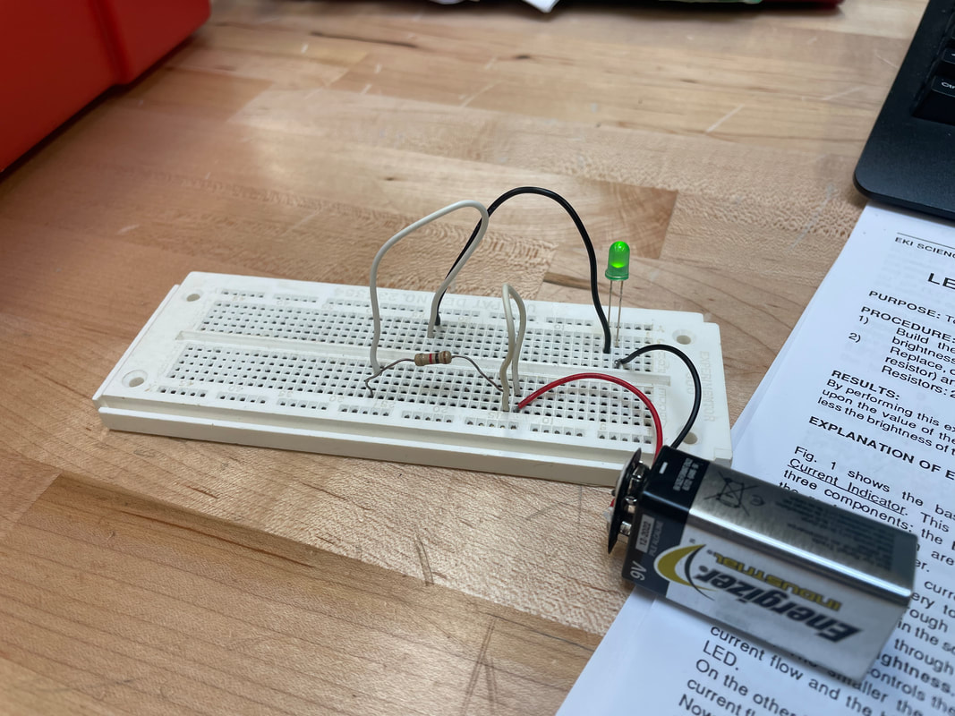
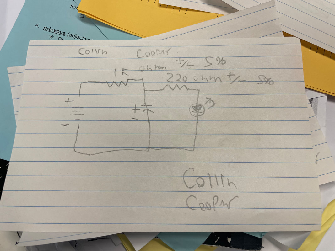
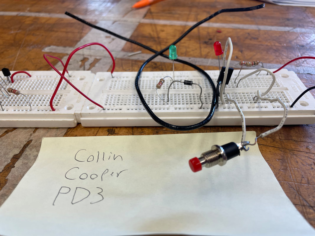
LAB 1 Current indicator
|
What: We were tasked with making a circuit for an LED light and a resistor. We were told to use several different types of resistors.
How: What I did, is I simply had the circuit go from the power supply, to the LED light, to the resistor, and back to the power supply, making a complete loop. Why: The main point of this lab was to show us one, how resistors work and the different strength levels of resistors. Two to show us what an LED light actually is. Three to show us the connections of a bread board. And four to show us the importance of creating a loop Further Feedback: Not really much to say, this was the simplest project we could've had without the entire circuit burning out. |
|
LAB 2 LED Brightness Control
|
What: The goal of this project was to make a LED light and a resistor that could be controlled to make the light dimmer or brighter.
How: I basically did the same thing as the last lab, Power supply to LED to resistor and then back to power supply, except one of the wires for the resistor was taken out. Why: This project was meant to teach us what a potentiometer is, how it works, and what it does. It also teaches us that it's not always bad to have a disconnected wire if it's done right Further Feedback: This project was honestly pretty cool, it was very interesting watching the light dim in my hands |
|
LAB 3 LIGHT ACTIVATED LED
|
What: The goal of this project was to make a light that would turn on when there's light, and turn off when there is darkness
How: This circuit was a tiny bit difficult for me to set up, mostly due to me not realizing that the LED I had in was burnt out and no longer working, but to sum up the project it was basically just two components, the LED and the Photo cell. The lab was very similar to lab one. Why: This labs main purpose was to teach us how to use photo cells, to teach us that photo cells are a type of resistor, and the different uses of a photo cell in electrical circuits. Further Feedback: This project was fairly interesting, it was cool seeing the resistance being controlled by light. It was a bit saddening that you could barely see a difference in the light though. |
|
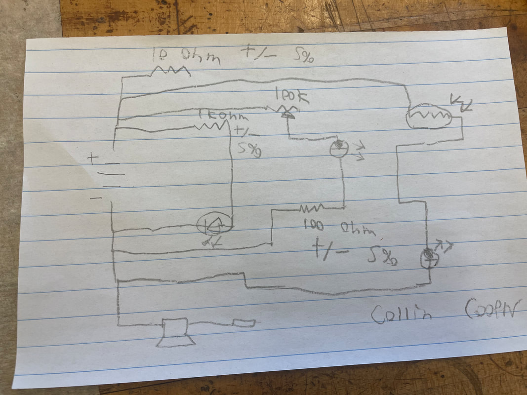
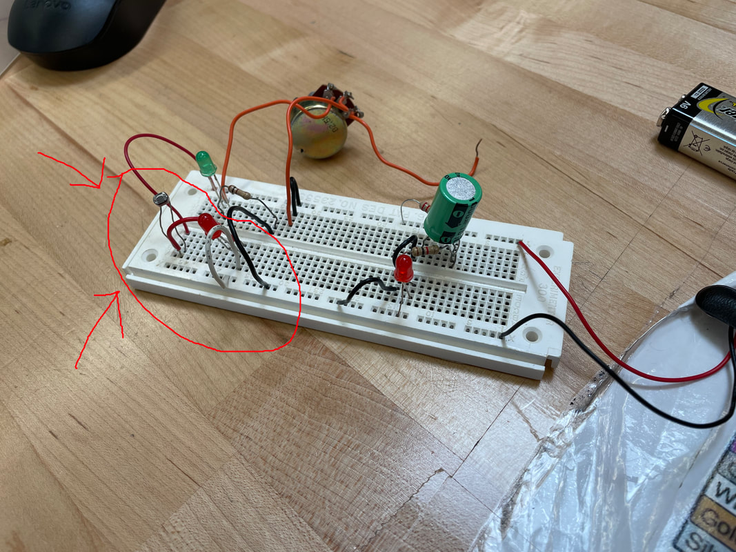
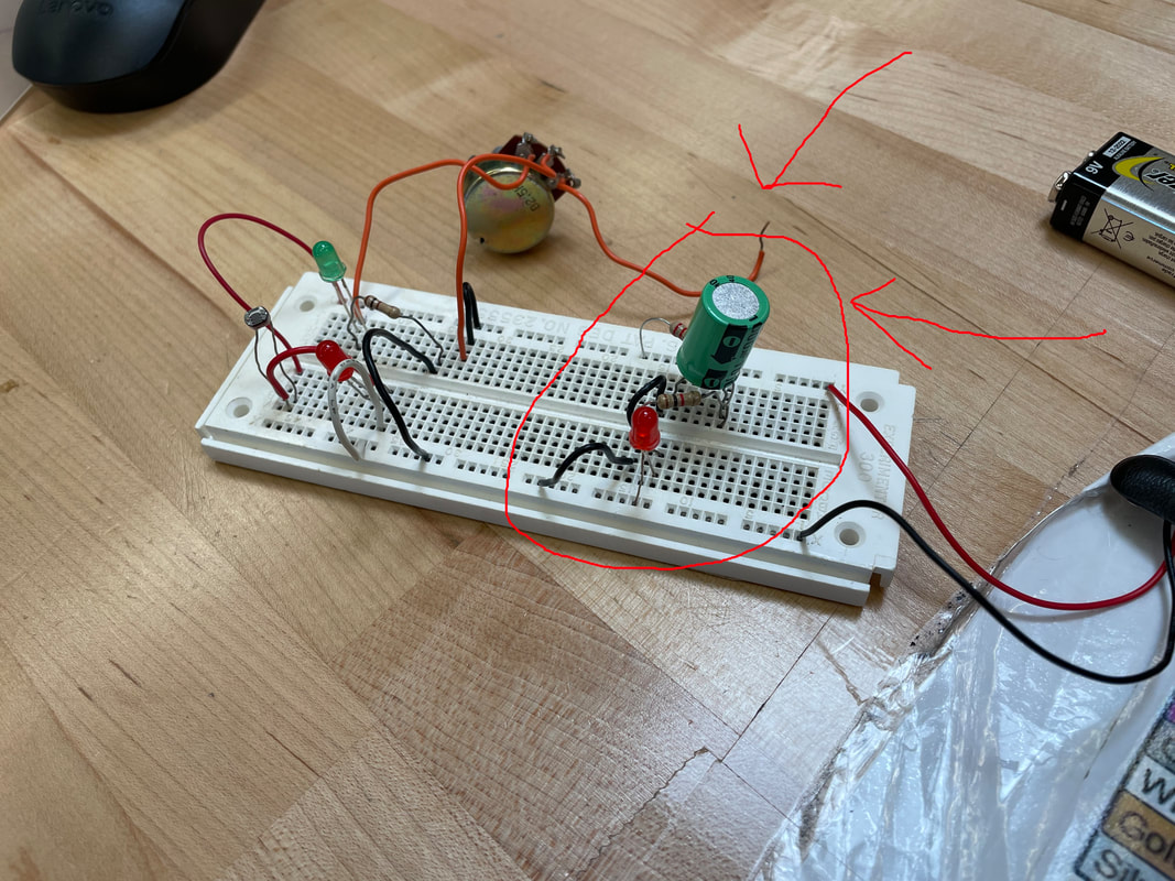
LAB 4 STORAGE OF ELECTRONS
|
What: Our job was to make a parallel circuit with two resistors, and LED, and one capacitor as shown on the right.
How: The project was very confusing at first, since it was set up in parallel, my first attempted ended up as a failure, but I eventually figured out how to put the capacitor in. Why: This project was mainly to show us that capacitors store electrons, so even when the power supply is removed, the light will still stay up. The lab also taught us how to hook up a circuit in parallel Further Feedback: This project was very frustrating, but it was needed so I could actually understand how to read plans better. |
|
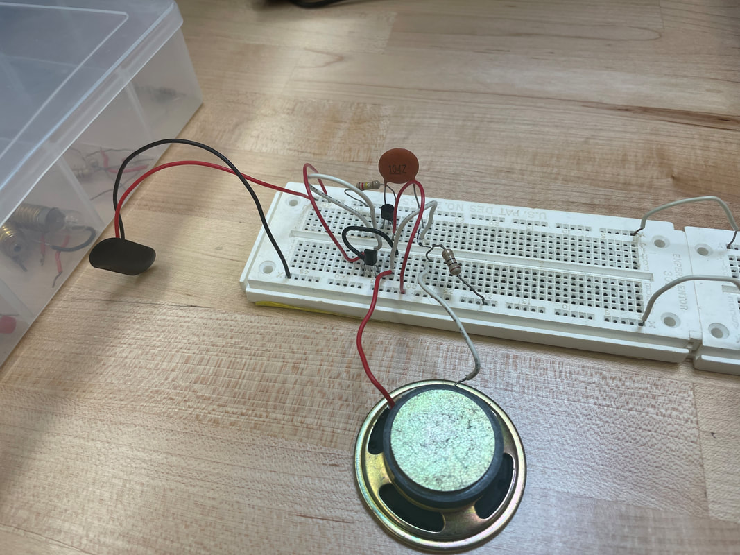
LAB 5 Speaker Action
|
What: The goal of this project was to make a working speaker.
How: What I had to do was, have a resistor coming off the negative side, and a speaker coming off the positive, neither connected to start out with. Then, when the battery is put in, we would rub the output wire to the resistor and the speaker would make static noises. Why: This project was to teach us how to use a speaker, how a speaker works, and how to electrically set up a speaker Further Feedback: This project was probably one of the simplest projects we have done and will do. Like the first lab it's really just two components. |
Labs 1-5 Video |
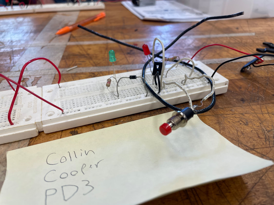
Lab 6 Diode Tester
|
What: The goal of this project is to make a basic circuit that includes a diode.
How: The process was very simple, all I had to do was repeat the schematic for lab 1, but we add a diode, and have to make sure that it, and the light diode are in the right position. Why: This project was mainly to teach us how a basic diode works, and that an LED is also a type of diode. We also learned what semiconductors are. Further Feedback: Honestly, this project was way too simple, and didn't really help to show what a diode is actually capable of. |
|
LAB 7 SCR Checker
|
What: The goal of this project was to make a circuit that includes an SCR and to check if it works.
How: This project was a pain for me, figuring out how to put the circuit together came with a lot of trial and error. Eventually I managed to get to SCR correct though. Why: The point of this project was to teach us how an SCR works. We also started getting into components with more than two prongs. Further Feedback: This project was really confusing for me, but that's just with semi conductors as a whole. |
|
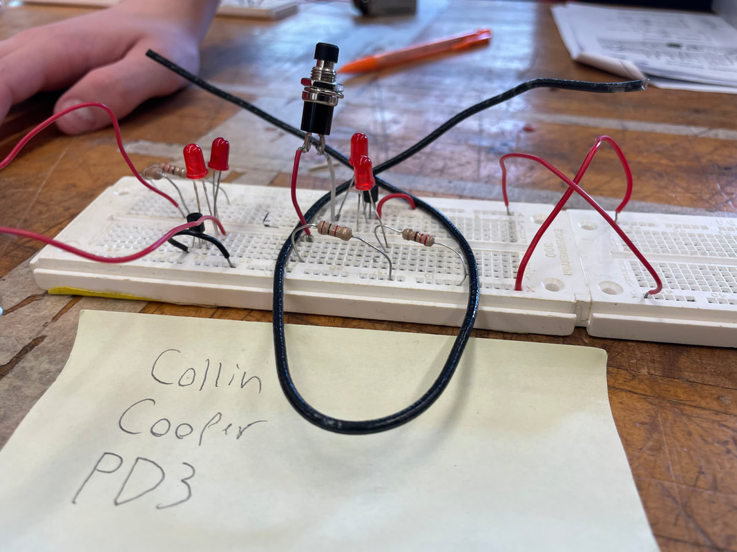
Lab 8 NPN Transistor Checker
|
What: The goal of Lab 8 was to make a circuit using an NPN that would have both lights turn on at the same time
How: This project also came with a lot of trial and error. But I switched the polarity of the power supplies so it would be easier to work with, eventually I got through. Why: The point of this project was to teach us how to use an NPN and further engross us in semiconductors Further Feedback: This project was pretty great. Not much I can say about it, it was a very sound project. |
|
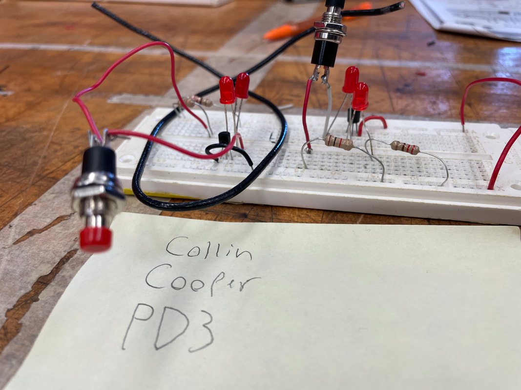
Lab 9 PNP Transistor Checker
|
What: The goal of this project is that we switch the NPN to a PNP, and now the lights are set up backwards.
How: This project was fairly simple. The only part that took a while was trying to set the PNP up the right way, which I eventually got correct through a little bit of trial and error. Why: The point of this project was to show us how changing the position of a diode can completely change how a circuit works. Further Feedback: This project is a great way of teaching us the importance of semi conductors and diodes. |
Labs 6-9 Video |
Lab 10 Transistor Oscilator
|
What: In this lab we had to make a speaker that would constantly make noise once it was turned on
How: When the circuit is turned on, current is constantly increasing and decreasing in the circuit, this causes the speaker to continuously make noise Why: This project was done to help us further understand how a speaker works, and to further engross us in the usefulness of transistors Further Feedback: This was a pretty solid project for us to do, it was also a really cool circuit to make |
|
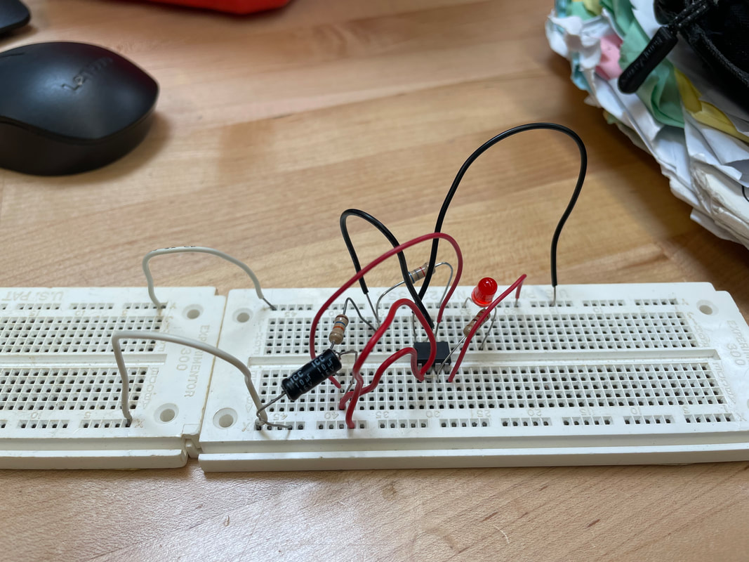
Lab 11 Blinking light Oscilator
|
What: The goal of lab 11 was to build an oscillator to make a light blink.
How: The whole project is centered around the 555 timer, which is a component with 8 prongs, we used all of the prongs except for the 5th prong. Why: The lesson that we can gain from this project is how a 555 timer works and can be used. Further Feedback: This project was really confusing on how exactly it works, I'm still struggling to figure it out. |
Lab 11 Video |
Lab 12 Automatic night light
|
What: The goal of this project was to make an LED light turn on when there was no light in a room.
How: It was very simple how I made this, there were three main components, the LED, the photocell, and the transistor. the photocell acts as a resistor as we found out before, but the LED turns on when there is light with the photocell. The transistor reverses the photocell and makes it lose its resistance when there is no light. Why: The lesson of this project was for us to understand how a photocell and a transistor can work together. Further Feedback: This project was a very cool and unique project; it was also very nice to be able to pick our own lab for this one. |
Lab 12 Video |
Lab 13 Use of power sources and meters
|
What: The goal of this project was for us to go through the packet assigned to us to find a further understanding of how the three different meters work and how to safely use them.
How: I used the components and my breadboard to recreate the exercises in the packet. Why: This lab teaches us how to use an ammeter, a voltmeter, and an ohmmeter. It introduces us to switches. And it gives us a better understanding of safety procedures. Further Feedback: This lab was fairly good, my only complaint being that it was hard to set up the ammeter with the switch, since there's no exposed metal on it. |
|
Lab 14 Sources of electricity
|
What: Our goal of this project was to see how different power sources (cells, photovoltaic cells, and couplings) work
How: This was also very straight forward, we followed the instructions m, and used the basic concepts of how a circuit works in order to set up the experiments Why: This was to teach us how to use different power sources, since a power source is a constant when working with electricity Further Feedback: This project very insightful, it caused me for once to have to think outside the box. |
|
Lab 15 Intro to switches
|
What: This goal of this project was to go through the packet and make all of the switch configurations we were given.
How: This project is very easy if you have common sense. You can generally tell what you need to do with the switch configurations, as long as you know how to read switch schematics of course. Why: This project, of course, was to teach us how to use switches. How to read switch schematics. And that the color of wires doesn't always matter to the circuit. Further Feedback: I think that this is one of my favorite projects, switches are a lot of fun to work with! |
LAB 16 Ohms Law
|
What: This lab had us go through the packet and make different kinds of circuits, and then we would use Ohms Law to figure out different values
How: There were three main algebraic equations we used, E divided by I = R, E divided by R = I, and I x R = E Why: The purpose of this project was to teach us how to effectively use Ohms law for with real circuits and real measurements Further Feedback: This project was very nice, it was fairly simple, with really the only struggle being finding the right resistors |
Lab 17 Power, heat, light
|
What: This project is pretty much the same as lab 16, just instead of calculating with Ohms law, we calculate with Watts law
How: The calculations for Watts Law are, E x I = W, W divided by E = I, and W divided by I = E Why: This project was used to make us understand both how to use Watts Law effectively, and to also understand the real world use of Watts Law Further Feedback: I really have no gripes with this project, I just like algebra I suppose |
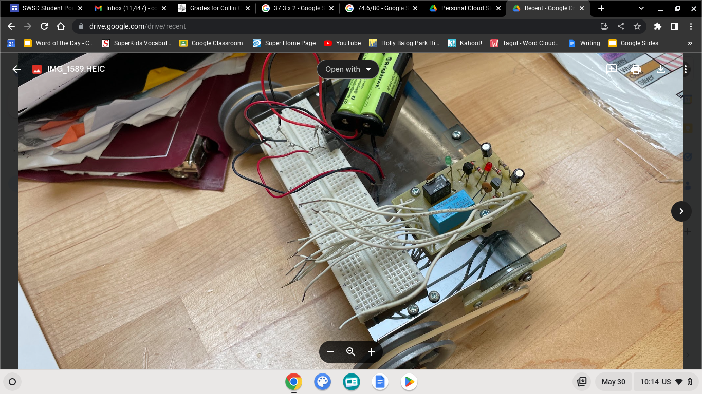
Robotics
|
What: The goal of this project was to complete 10 of the labs found in the robotics packet.
How: Most of the labs all I did was switch around the polarity for the motors to create different effects. The last two labs however I wasn't able to do, mostly due to the relay board not working, and then on top of that, the rubber bands were not actually strong enough to move the robot. Why: The purpose of this lab is to teach us how electronics can be created to connect with a remote control, and how they can be used to create something that moves. Further Feedback: It'd be nice if we were given components that actually worked, and if we also had the right rubber bands to do the job with. |
|
Conclusion
|
In conclusion, I have learned many things and gained many during this semester with Mr Sieg, such as.
The ability to read electronics schematics and to put together a circuit accordingly. The ability to use meters such as the voltmeter, ammeter, and ohmmeter in order to make measurements for my circuits, components, and connections. The ability to have a theoretical understanding of the inner workings of my circuits and components when it comes to the concepts of amperage, voltage, wattage, and resistance and how they all intertwine together. |
|
